
Blog 6: Project Development
- darelsuen
- Feb 19, 2023
- 6 min read

Updated: Feb 21, 2023
In this page, I will:
1. Briefly describe my team chemical device
2. Show how the team planned, allocated the tasks, and executed the project.
3. Document the entire design and build process of the chemical device and
include videos, pictures, and screen captures of the processes.
4. Include “Hero shot” of every milestone of the processes, example the part A
that was 3D printed, part B that was laser-cut, electronics components
moved/worked according to the program. Hero-shot is taken with the person-
in-charge holding/working/making the parts.
5. Include the name of the person who was in-charge of every part of the project.
6. Document my individual contribution to this project.
7. Provide the link to the page of the blog of my teammates.
8. Describe problems encountered and how the team solved them.
9. Include all the project design files as downloadable files.
10. Embed the final prototype design file, i.e., the final fusion360 design file
showing the entire prototype.
11. Type my Learning reflection on the overall project development
1. Our team Chemical Device
In this section, I will briefly describe my team chemical device.
What it is. What problems will the chemical device solve?
My team's chemical device is a tea maker. Our tea maker was inspired by existing electric tea kettles. Our device is a platform similar to that of the base of an electric kettle consisting of a casing covering a circular plate connected to a load cell, a temperature sensor, an Arduino board, wires and a breadboard. Unlike existing electric kettles, we couldn't put a heating element inside as it is apparently 'unsafe'.
The load cell measures the weight placed on the plate and with density, is proportionate to volume. The program for the load cell tares when it is reset. The LCD display shows the temperature and volume given by the signals of the electrical parts.
There is also a stand with a continuous servo attached to a wheel on top that acts as a pulley to pull the metal filter from the teapot with a press of a button to lift it up or down and to stop the servo.
Below is the hand sketch of the chemical device.

The pulley stand isn't in the sketch as our initial mechanism was going to be a simple servo pressing the lid of the teapot to open the lid. However, the servo arm could not grip the lid of the teapot without using attachment methods. However, if we glued the servo arm onto the tea pot, it wouldn't be removal and we wouldn't be able to even pour the tea.
2. Team planning, allocation and execution
In this section, I will list down my team member's name and their respective roles (CEO, CFO, COO, CSO)
Long Jingxuan Kerri (CEO)
Kelvin Ang (COO)
Dylan Low (CFO)
Suen Ka Chun Darel (me) (CSO)
Nur Firzanah Binte Roslan
I will show the finalized BOM (BILL OF MATERIALS) table.

I will show the finalized Gantt chart (planned and actual) and the tasks allocation for each team member
3. Design and Build process
In this section, I will provide documentation of the design and build process
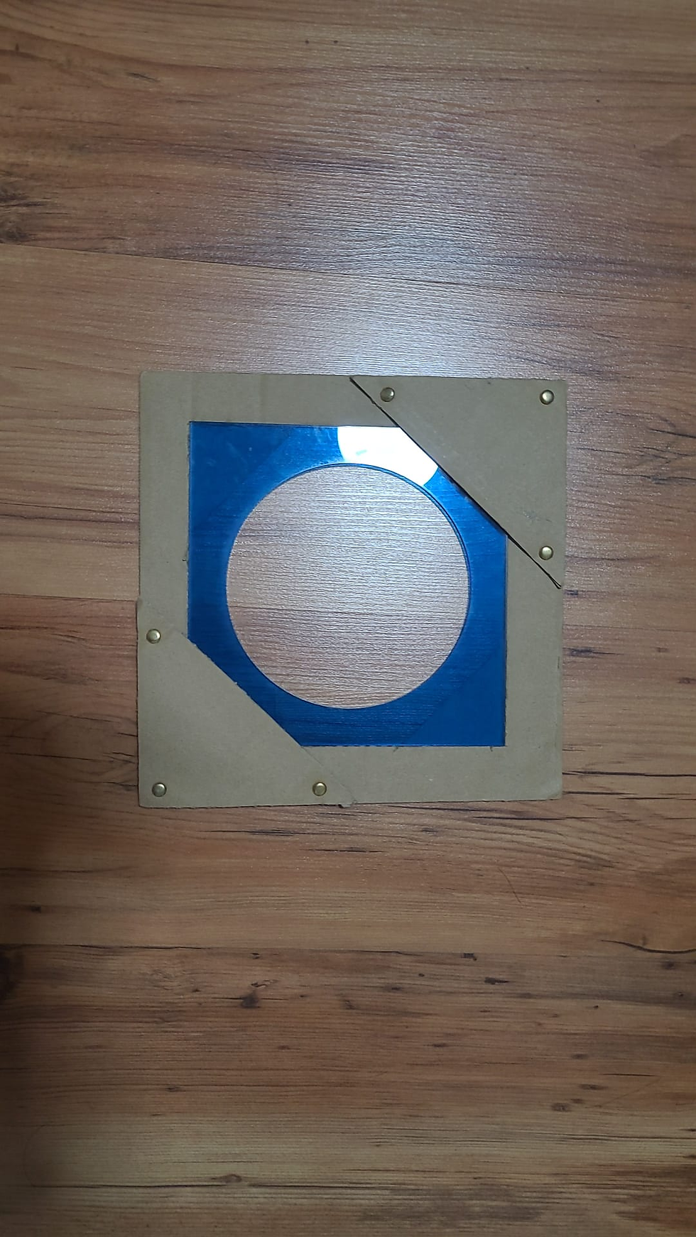
Part 1. Design and Build of Load Cell Base and Plate (Done by ME, Dylan & Firzanah)
My main contribution was the dimensions and rough prototyping of the load cell base. This involved gluing and cutting cardboard together to estimate the dimensions of the base so that all of our 3D printed components and other electronics could be fit inside. I also cut a few pieces of cardboard and glued them together to act as a counter weight for the load cell as our 3D print was a bit uneven so that the plate could be fitted on nicely.

^ Cardboard glued to the 3D prints
After a lot of cardboard and hot gluing, the base for the load cell was done.

The base is a square base with a length of 238mm and a height of 60mm.

The length of the LCD was 72mm and the breadth was 27mm.

Thankfully all of the electronics fit snuggly.

^Hero Shot
Part 2. Programming of load cell, temperature sensor and LCD (Done by Dylan & Kelvin)
Dylan's Blog: https://dylanl21.wixsite.com/cp5070-2022-2b02-gro/post/blog-6-project-development
Kelvin's Blog: https://cp5070-2022-2b02-group2-kelvinang.blogspot.com/
Part 3. Laser cutting acrylic parts (Done by Firzanah)
Firzanah's Blog: https://cp5070-2022-2b02-group2-firzanah.blogspot.com/
Part 4. Design and build of casing (Done by Dylan & Kelvin)
Dylan's Blog: https://dylanl21.wixsite.com/cp5070-2022-2b02-gro/post/blog-6-project-development
Kelvin's Blog: https://cp5070-2022-2b02-group2-kelvinang.blogspot.com/
Part 5. Design and build of servo stand (Done by Firzanah & Kerri)
Firzanah's Blog: https://cp5070-2022-2b02-group2-firzanah.blogspot.com/
Kerri's Blog: https://cp5070-2022-2b02-group2-kerri.blogspot.com/
Part 6. Programming the servo (Done by Kelvin)
Kelvin's Blog: https://cp5070-2022-2b02-group2-kelvinang.blogspot.com/
Part 7. Integration of all parts and electronics (Done by ME)
Once all the parts and pieces were complete, it was time to assemble them.

The first part to assemble was the base. It was assembled by inserting the laser cut into the cardboard pockets of the base plate. The cardboard pockets were attached using pins.

Then the electronics were inserted and the base plate put on top.


The stand was next and assembly began by slotting two laser cut pieces into a cardboard piece with a tab.

Next, the pulley wheel's string is attached to the tea filter of the tea pot.


Next the head of the stand attaches to the pole of the stand. The pulley wheel goes into the head and the servo goes into its housing on the outside of the head.


^Our completed product :)))

^Hero shot
4. Problems and solutions
In this section I will describe the problems encountered in the design and build process and how the team solved them.
The first problem our team faced during our initial mockup was actually a lack of mechanism. As we designed the teamaker based of something that already exists, we had to think quickly on how to make our product more innovative and novel. As I was the one who did the sketch in the CA2 part 1 that was eventually chosen. I was tasked to think of an idea. My initial idea to to use a servo to flick the tab on the lid of the tea pot to open it. However, after many trials, we could not get the servo to reliably open the teapot lid without using adhesives to bind the servo arm to the teapot. As such the idea was scrapped. However, the team was able to work around the problem using what we had and we thought of using the servo to power a sort of pulley system that would remove the tea filter from the tea pot. Unfortunately, I was not able to see the whole development process of our mechanism as I was sick for quite a while. My eyes decided to go all funky and decided to blur my vision by increasing the pressure inside them. I even had to miss the CEDC Test 2 because of it.
Coding the arduino was also quite the challenge for my group mates. The LCD screen and the temperature sensor refused to work together no matter how many times Dylan and Kelvin tried to code them. After changing literally every part we had (arduino, sensor, LCD), they decided that the code may have been the issue and used a different one.
3D printing was also quite the challenge as we had a few failed pieces and our prints were not very clean as well. But I chalk it up to the printers in W3 being rather faulty. We overcame the challenge by simply trying to 3D print our pieces whenever possible and filing down the pieces that were a little rough.
5. Project Design Files as downloadable files
In this section, I will provide all the design files (Fusion360 files, .dxf files, .stl files, arduino programs files) as downloadable files.
All the files used for my team's prototyping journey is on the google drive link below.
6. Below is my Learning Reflection on the overall Project Development.
The product development journey has been quite a tiring but insightful one. To be honest, I severely underestimated how difficult this would be as I only had the journey I experienced in ICPD to compare. The level of difficulty between ICPD and CPDD is honestly night and day. There are so many new things we have to consider when actually beginning to prototype our product that I never experienced in ICPD. There were many hiccups during our product development journey that could be solved as this was only a prototype but I now realize how much of a headache it would be for an actual product.
Things like the Bill of Materials (BOM) was something I did not initially see the importance of as the parts of our prototype were relatively inexpensive. However, on a large product being produced in a mass scale, it is absolutely important as the finances of company really dictates how successful the product will be. If the product costs too much to manufacture, the selling price will be too high and no one would buy it.
Teamwork wise, I felt that communication was very lacking in my group. It was partially my fault as I was ill during the end stage of the product development and could not facilitate communication between my team even if I wanted to.
The journey has been extremely insightful as it taught me skills besides purely engineering. Things like communication, management and team work were takeaways that I feel were the most valuable as they apply to all working fields even beyond engineering. My biggest regret during the whole product development journey was not being able to be there with my group during the end stage of our prototyping as I did not want to risk getting glaucoma in my eyes as one of my future aspirations depends on my eyesight. However, I am still proud of what my group and I have accomplished no matter the setbacks or the outcome. I hope to put the skills and knowledge I have gained into my future career or further education.


Comments